
Ready for the future,
caring for the customer
INSPECTION SCENERY DEFINITION
TRAJECTORY DESING AND PROGRAM GENERATION
COMPONENT DEFINITION
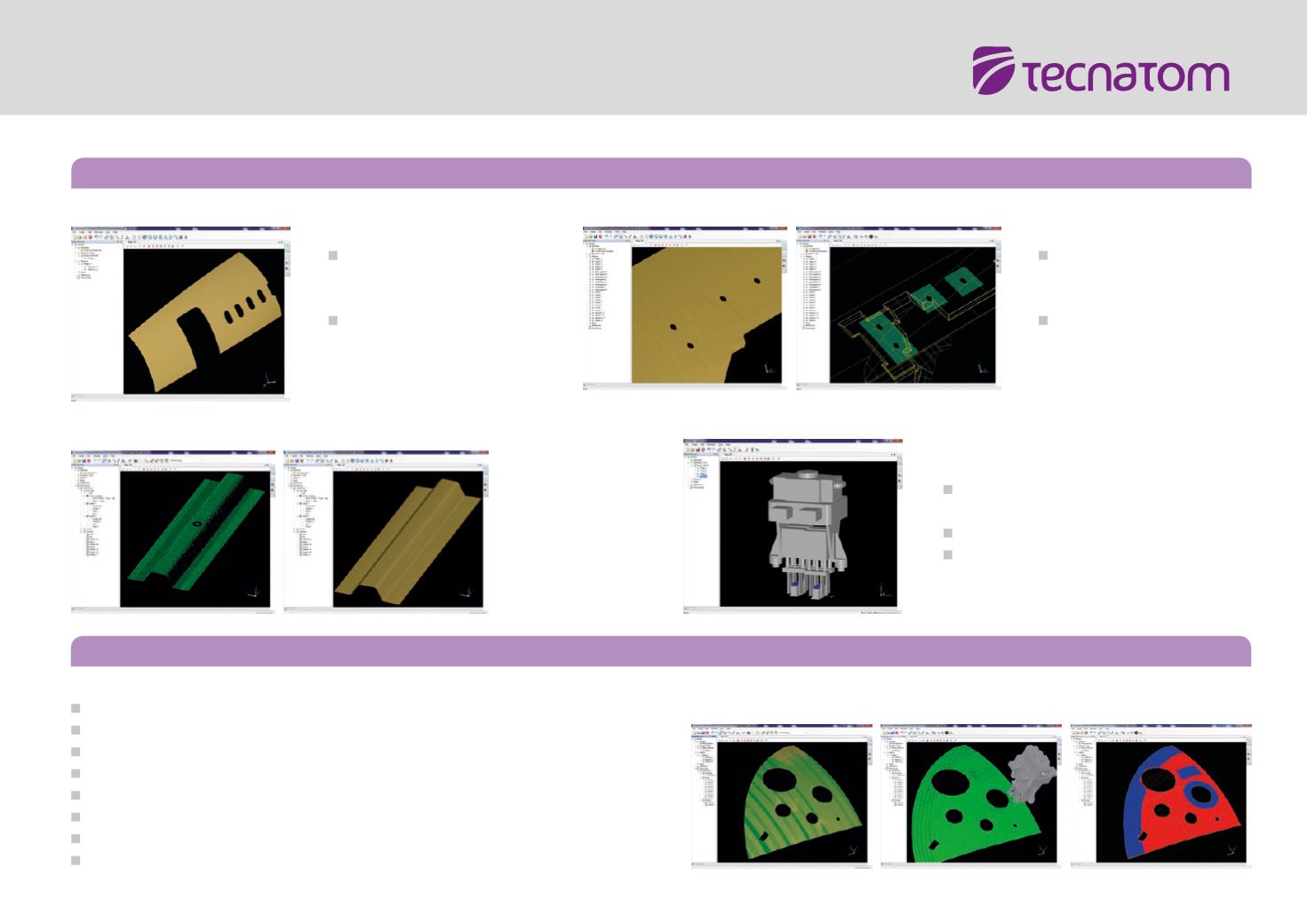
Import component CAD
files in exchange formats
STEP and IGES
Reconstruction of surfaces
from point clouds
Design trajectories in the 3D viewer by mean of aided strategies
Tune-up designed trajectories with a full catalogue of edition and design tools
Customizable reorientation of inspection tool
Validate trajectories by simulation and coverage estimation tools
Double inspection tool positioning in 3D according front and rear surfaces
Trajectory sampling according to system needs and surface complexity
Generate machine language trajectory program by processing the sampled trajectory
Support for kinematic calculations of mechanical equipment
REGIONS DEFINITION
Definition of custom
inspection regions in which
trajectory will be designed.
Trajectories belonging
to different regions can
be included in the same
trajectory program.
INSPECTIONTOOL MODELING
Import CAD files defining the shape of
inspection tool
Model the probes at the inspection tool
Exchange tool models between Gentray 3
projects


